Architectural Aspects
Apartments and housings
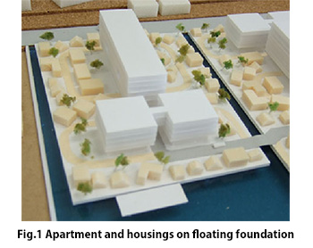
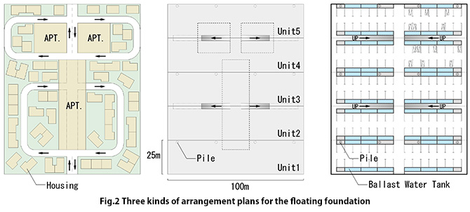
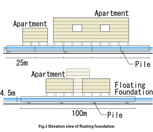
As an example shown in Fig.1, we take the typical residential houses on the floating foundation consists of 5 modular units (100 m x 25 m, in 5 individual units). As is shown in Fig.2B, five floating foundations are joined together by welding in line with the Mega-float Project demonstrations. In the architectural arrangement the medium-sized apartment housings and low-rise private residences are situated on the floating foundation (see Fig.2A) while the car-parks, roads and the ballast water tanks are located inside of the floating foundation (see Fig.2C). Several medium-sized buildings including about 150 residences and approximately 60 low-rise private houses can be built on the steel-made floating foundation (100 m in width and 125 m in length) of 3.0 m draft condition ( corresponding to the displacement of 37,500 t) including roads and open spaces. In this case, on the floating foundation, the medium-size apartments with shops on the first floor cover a total floor area of 11,600 ㎡ and the private houses cover an area of 7,200 ㎡. The elevation view of the floating foundation with apartments and housings is shown in Fig.3.


On the prototype floating foundation consists of 5 modular units (100 m in width, 125 m in length, 3.0 m in draft and 4.5 m in total height), the medium-size apartment housings with shops on the first floor cover a total floor area of 11,600 ㎡ and the low-rise private houses cover an area of 7,200 ㎡, with a total weight of 16,600 t for the former and 10,655 t for the latter. In this computation, the load of 1 m2 of a light-weight reinforced concrete building was used as 1.48 t/ m2 which is obtained from the fundamental study. Accordingly the total weight of the apartments and private houses is brought to 27,255 t. On the other hand, the dead weight of the floating foundation consists of 5 modular units is estimated as 9,390 t from the data provided by the Mega-float Project (0.167 t/ m3). The live load of items such as trees, asphalt and cars is assumed as 1,750 t in this study. Moreover, since this live load varies depending upon quantity, materials and so on, the design enables the adjustment of one fifth of the total live load by regulating the volume of ballast water (the maximum volume of ballast water is 7,500 m3 or 7,500 t in weight) inside the floating foundation.
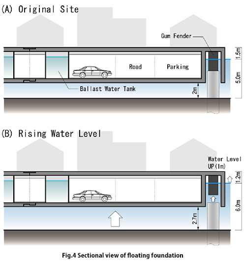
In principle, the floating foundation floats by itself but the proposal calls for what is known as the "Soft Landing System (See Fig.4)". In this system, the floating foundations are semi-supported by support piles constructed underneath. The buoyancy provided by the floating foundations serves to lighten the load on the support piles. Laterally mounted support piles connected to the sides of these floating foundations feature rubber fenders that assist in the control of the horizontal excursion of these floating foundations. Since approximately one tenth of the total load is supported by several concrete piles, the final total load of the floating foundation comes to 41,250 t (37,500 t is supported by the buoyancy force of the floating foundation while the supporting piles add 3,750 t). When there is an unexpected increase in water level due to the floodwater from heavy rains and so on, the floating foundation can easily change its position up from the soft landed condition. In the case of 1 m increase in water depth, the draft of the floating foundation becomes 3.3 m instead of 3.0 m when the floating foundation floats independently as is shown in Fig.4.


